
Materials with controlled architectures at the nanometer scale can have dramatically improved optical, mechanical, and transport properties compared to their bulk counterparts. However, it has been difficult to maintain nanoscale control of material architecture for samples larger than cm². We seek to use a combination of self-assembly and scalable manufacturing technologies to enable manufacturing of m² of material while controlling nanoscale geometry and chemistry.
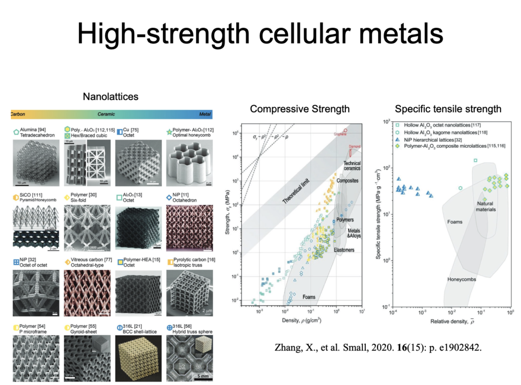
High-strength nanostructured cellular solids
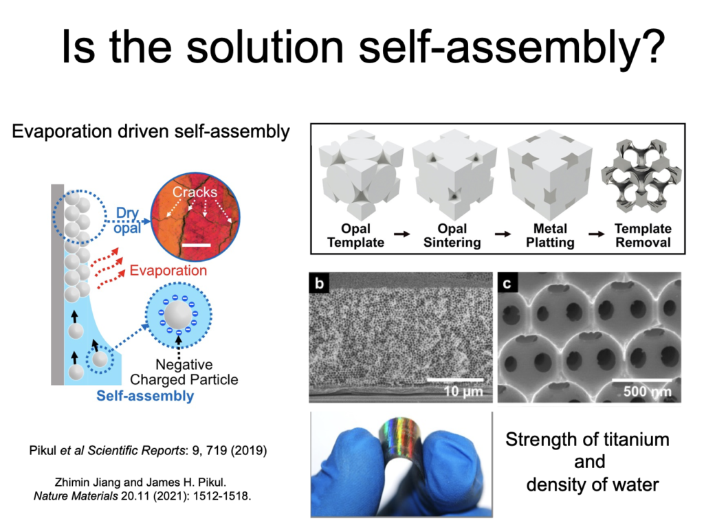
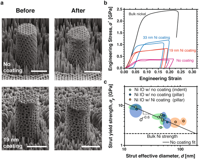
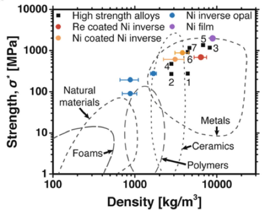
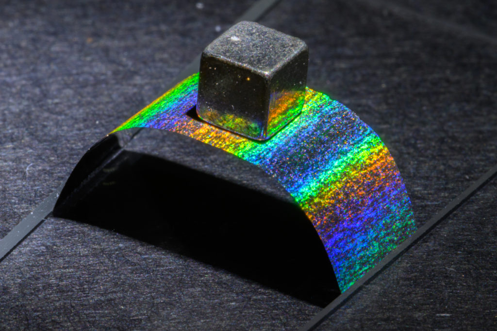
We have developed a nickel-based cellular material which has the strength of titanium and the density of water (Fig. 1). The material’s strength arises from size-dependent strengthening of load-bearing nickel struts whose diameter is as small as 17 nm and whose 8 GPa yield strength exceeds that of bulk nickel by up to 4X (Fig. 2). The mechanical properties of this material can be controlled by varying the nanometer-scale geometry, with strength varying over the range 90–880 MPa, modulus varying over the range 14–116 GPa, and density varying over the range 880–14500 kg/m3 (Fig. 3). We refer to this material as a “metallic wood,” because it has the high mechanical strength and chemical stability of metal, as well as a density close to that of natural materials such as wood. In addition, its cellular nature allows for future multifunctional material integration.
Understanding how cracks form in self-assembled particles
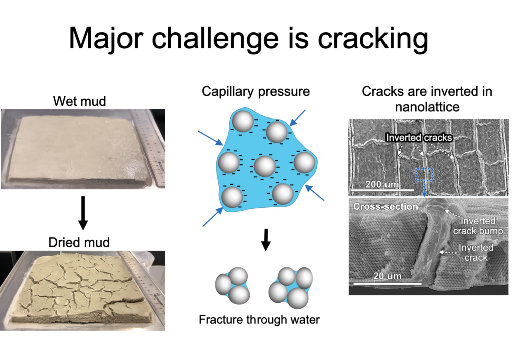
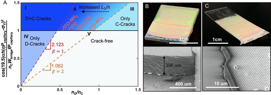
Cracking in the drying opal templates used to fabricate inverse opals, however, is a major hindrance to the use of self-assembled nanolattices for practical and fundamental studies. In work published in ref. [25], we conduct desiccation experiments on polystyrene particle opals self-assembled on indium-tin-oxide coated substrates to study their fracture mechanisms, which we describe using an energy-conservation fracture model. The model incorporates film yielding, particle order, and interfacial friction to explain several experimental observations, including thickness-dependent crack spacings, cracking stresses, and order-dependent crack behavior. Guided by this model, we are the first to fabricate 120 μm thick free-standing metallic inverse opals. This work improves our understanding of fracture mechanics in drying particle films, provides guidelines to reduce crack formation in opal templates, and enables the fabrication of free-standing large-area single-crystal inverse opals.
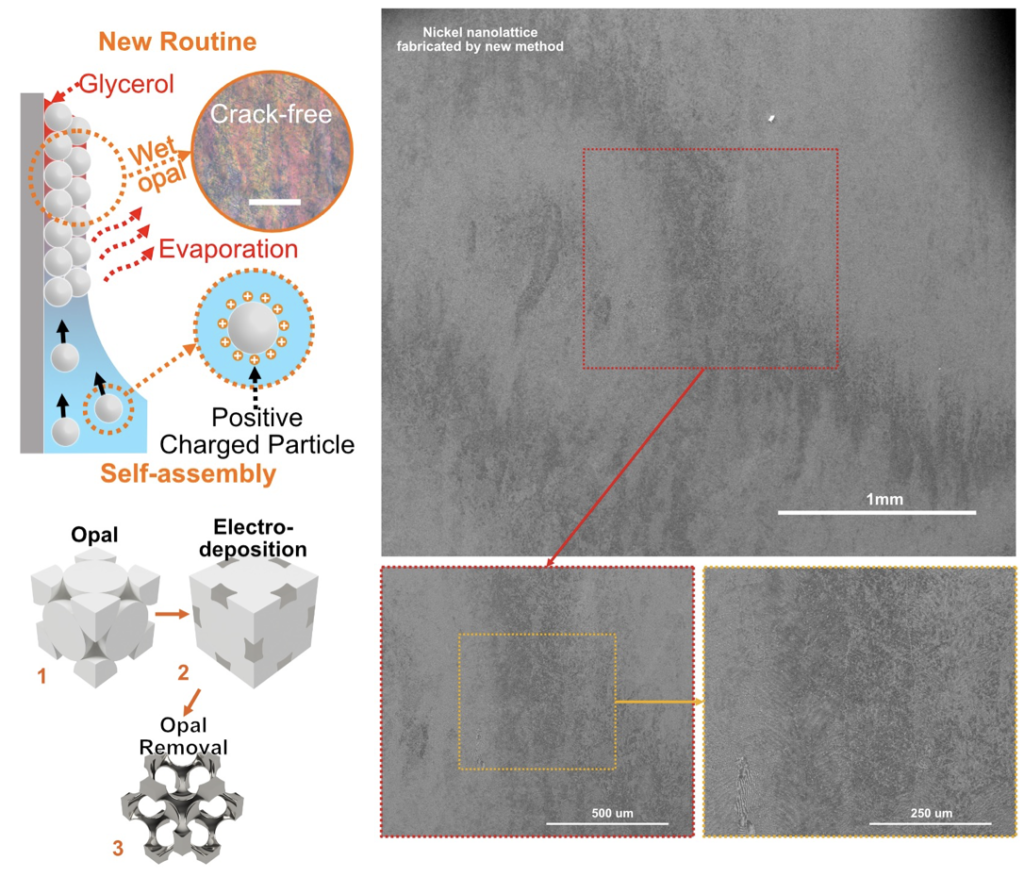
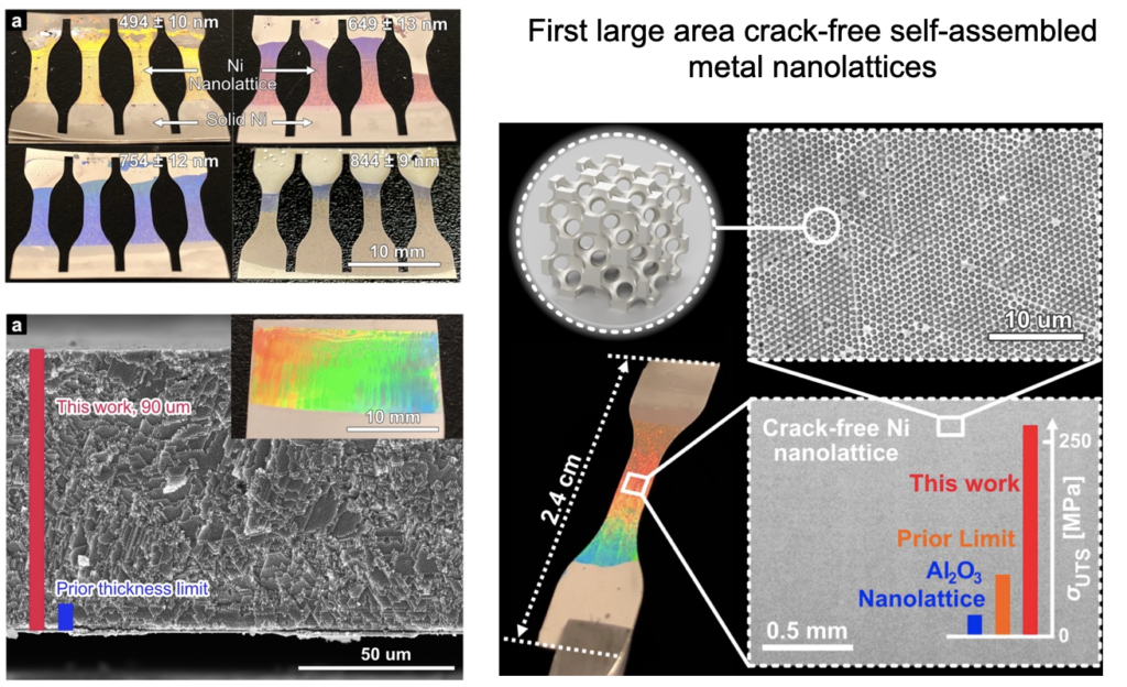
Enabling large area crack-free nanolattices with record strength and scalability
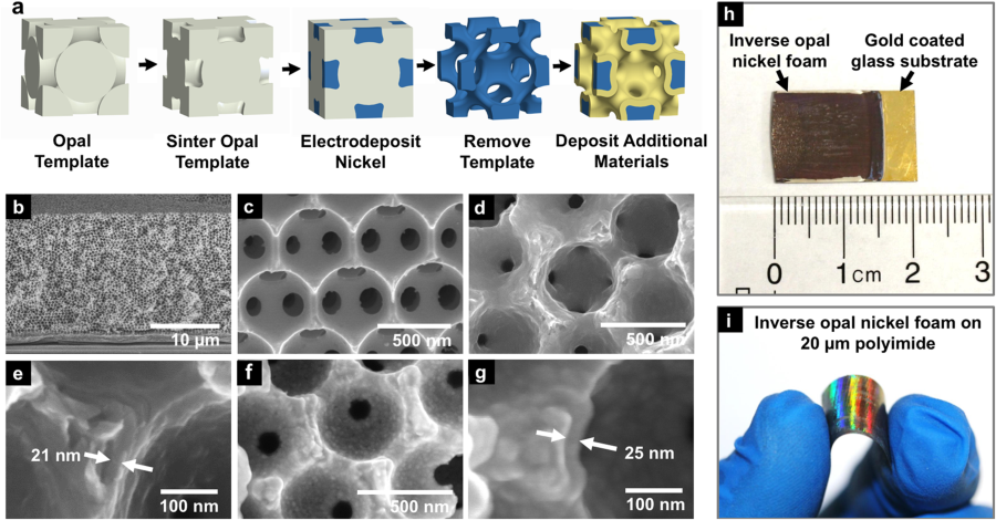
In work published in Nature Materials (Ref. [30]), we demonstrate a crack-free self-assembly approach to fabricate cm-scale multifunctional metallic nanolattices with 100 nm periodic features and 30 nm grain sizes, which corresponds to a 20,000X increase in crack-free area and 1,000X the number of unit cells in the loaded direction than prior nanolattices. These nanolattices have 257 MPa tensile strengths at 1.12% strain and a density of 2.67 g/cm3, which is 2.6 times the strength of the strongest porous metals with the same relative density at any scale. We eliminated cracks during self-assembly by maintaining a wet template and utilizing electrostatic forces to assist metal electrodeposition through the template. The resulting nickel nanolattices have excellent photonic coloration and approach their macroscopic theoretical tensile strength. The high absolute strength and the low density would allow nickel nanolattices to replace sandwich panel cores with 50% smaller volume than porous titanium, 50% lower mass than porous iron, and, importantly, 10X less volume than other nanolattices.
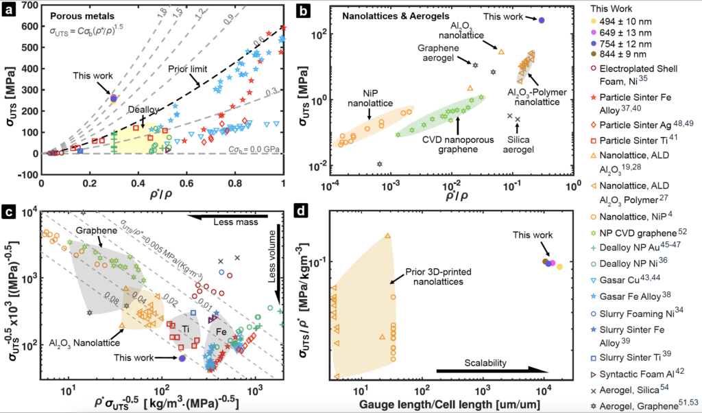
 from 0 to 1.8 GPa. The black dashed line denotes the empirical limit of prior fabrication methods, including particle sintering, dealloying, Gasar, slurry foaming, and syntactic foaming. (b) Ultimate tensile strength versus relative density of nanolattices, nanoporous graphene, and aerogels. (c) Characteristic volume (
 -1/2) versus characteristic mass (ρ*-1/2) of a rectangular beam to bear a bending moment for different porous materials. The dashed lines are defined by specific tensile strengths between 0.005 and 0.08 MPa/(kg·m-3). (D) Specific tensile strength versus the ratio of sample loaded length to unit cell length of nanolattices. From Ref. [30]
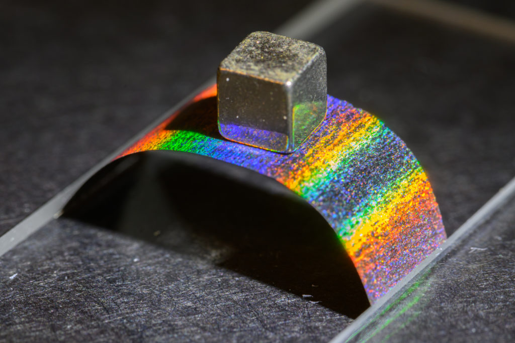
Publications:
[30] Zhimin Jiang and James H. Pikul. “Centimetre-scale crack-free self-assembly for ultra-high tensile strength metallic nanolattices” Nature Materials, 1-7, 2021.
[25] Zhimin Jiang, Zakaria Hsain, and James H. Pikul. “Thick free-standing metallic inverse opals enabled by new insights into the fracture of drying particle films” Langmuir, 2020.
[18] James H. Pikul, Sezer Özerinç, Burigede Liu, Runyu Zhang, Paul V. Braun, Vikram S. Deshpande, William P. King, “High strength metallic wood from nanostructured nickel inverse opal materials“, Scientific Reports, vol. 9, January 2019. Top 100 downloaded materials science papers for Scientific Reports in 2019.
[8] James H. Pikul, Paul V. Braun, and William P. King, “Micromechanical devices with controllable stiffness fabricated from regular 3D porous materials”, Journal of Micromechanics and Microengineering, vol. 24, 105006, 2014